

Every liquid-cooled rack depends on one box most people outside the industry have never heard of: the coolant distribution unit, or CDU. Also written as a cooling distribution unit, it moves coolant between the building's chilled water system and the servers, and everything between the CDU and the cold plates — pumps, manifolds, tubing, sensors — lives or dies by how well the loop holds pressure, stays clean and can be serviced without draining everything.
Valves are a small line item in a CDU bill of materials. They are also the part that decides whether a technician can swap a pump at 2 a.m. without taking a rack offline. This guide walks through where valves sit in a CDU and its secondary fluid network, what to specify, and which mistakes show up after commissioning rather than before.
What a coolant distribution unit does
A coolant distribution unit is a pumping and heat-exchange station that separates the facility water system from the coolant loop that actually touches the IT hardware. Facility water on one side, treated coolant on the other, a plate heat exchanger in between. The CDU controls flow, temperature and pressure on the IT side, so server cold plates never see raw facility water.
That separation is the whole point. Facility loops run open towers, mixed metals and water chemistry a cold plate was never designed for. The CDU gives the IT side its own closed, controlled loop — which the industry calls the secondary fluid network. The Open Compute Project's Cooling Environments group publishes the guidelines most hyperscale designs reference for exactly this architecture.
In-rack, in-row and liquid-to-liquid
CDUs come in three main formats, and the format decides how much room you have for serviceable components like valves.
| CDU format | Where it sits | Typical duty | Valve implication |
|---|---|---|---|
| In-rack CDU | Inside the server rack, takes rack units | One rack | Compact — small-bore threaded valves, tight service access |
| In-row CDU | A floor-standing unit serving a row | Several racks | Larger bore, more room; isolation at every rack takeoff |
| Liquid-to-liquid CDU | Between facility water and the SFN | Row to room scale | Both loops need isolation and drain points at the unit |
All three formats share the same fluid problems. The differences are bore size and how far the secondary loop stretches.
An in-rack CDU earns its place when liquid cooling arrives one rack at a time — a retrofit into an air-cooled room, a pilot deployment, an edge site. It occupies rack units that could hold servers, so everything inside is packed tight: heat exchanger, pumps, controls and the loop connections all live in a few U of height. For the valve specification that means small-bore threaded connections, short handles that clear neighbouring components, and a strong preference for parts that never need attention, because reaching them means pulling the unit forward on its rails.
An in-row CDU is a floor-standing cabinet serving several racks — the format most dedicated AI build-outs settle on. It has room for duty and standby pumps, proper instrumentation and maintainable plumbing, and it pushes the secondary loop out along the row through supply and return headers. The valve count rises with the reach: every rack takeoff wants its own isolation point, and the CDU connections themselves move up in bore to carry the row's full flow.
A liquid-to-liquid CDU at row or room scale is where the unit behaves like plant equipment. Both sides of its heat exchanger are serious water circuits, and both deserve the treatment a mechanical engineer would give any plant loop: isolation on entry and exit, drain points, strainers ahead of rotating equipment. When people search for a cdu data center design reference, this is usually the scale they mean — and it is the scale where skipping a five-dollar valve creates a five-hour outage.
The secondary fluid network, briefly
The secondary fluid network (SFN) is the closed coolant loop on the IT side of the CDU: supply and return manifolds running up the rack, branch lines to each server, cold plates over the processors, and back. Rack manifolds distribute coolant to dozens of servers; quick disconnects let a single server drop out without opening the loop.
Because the loop is closed, whatever is in it stays in it — including anything corrosion puts there. Cold plate channels are narrow enough that particulate is a first-order design concern, which is why fluid quality and wetted-material selection take up so much space in the OCP guidelines. The U.S. Department of Energy's Lawrence Berkeley National Laboratory tracks liquid cooling precisely because these loops move most of a modern AI rack's heat.
Coolant manifolds and quick disconnects
The rack manifold is the spine of the secondary loop: a vertical pair of supply and return headers, usually stainless, running the height of the rack with a branch connection per server. Rack manifold liquid cooling designs live or die on connection count — a 42U rack can carry dozens of branch lines, and every one is a potential leak path directly above electronics. That is why manifold builders weld what can be welded, gasket what cannot, and put a quick disconnect at the server end so a node can be swapped without tools or spillage.
Quick disconnects are precision components with their own suppliers, and they solve the per-server problem. What they do not solve is the per-branch and per-rack problem: a dripless coupling lets you pull one server, but only an isolation valve lets you shut down one branch, one manifold or one CDU while the rest of the room keeps computing. The two components are complements, not substitutes — CDU components lists that include one and omit the other tend to get corrected in the second build, after the first loop has had to be drained for a single stuck coupling.
Where the loop is hard-plumbed — CDU internals, header runs, row piping — weld-end stainless valves remove even the threaded joint as a leak path. The same serviceability logic applies as everywhere else in the loop: our pneumatic butt weld ball valve exists precisely because some builders want the welded line and remote actuation in one component; the manual extended butt weld ball valve is the same body worked by hand.
Where valves sit in the loop
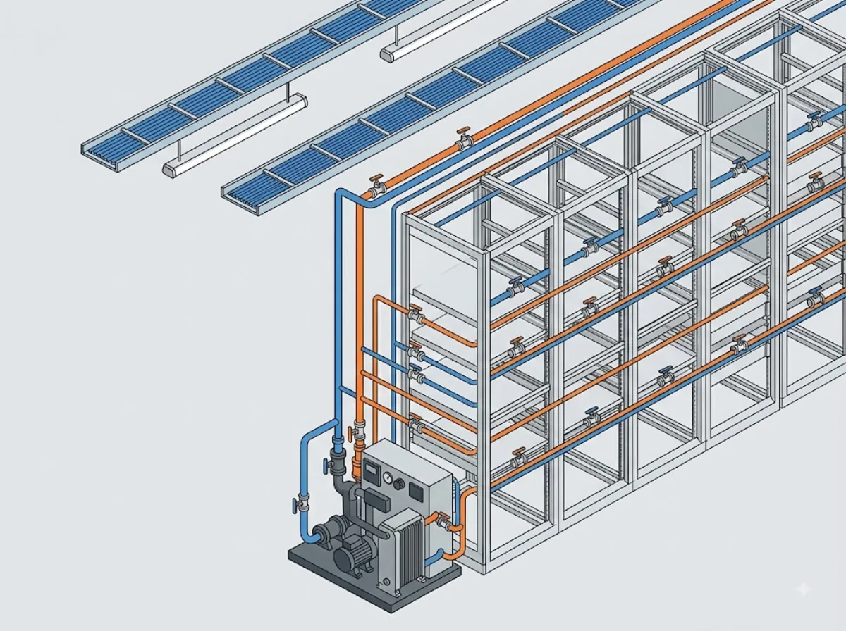
Short answer: at every point where something will eventually need to be isolated, drained, vented or protected. In practice that means five places.
| Position | Valve type | What it is there for |
|---|---|---|
| CDU supply and return connections | Full port ball valve | Isolate the CDU for service without draining the loop |
| Rack manifold takeoffs | Small-bore ball valve (1/2″–1″) | Shut one branch while the rest of the row keeps running |
| Pump discharge | Swing check valve | Stop reverse flow through the idle pump in duty/standby pairs |
| Loop low points | Drain ball valve | Controlled fill and drain instead of cracking fittings |
| Upstream of pumps and instruments | Y strainer | Catch commissioning debris before it reaches pump seals and cold plates |
The check valve position deserves a note. CDUs run redundant pumps, and when one pump idles, the running pump will happily push flow backwards through it. A horizontal swing check valve on each discharge closes on gravity and reverse flow — no power, no setting, nothing to fail. The same logic applies to the strainer: a Y strainer on the suction side is cheap insurance for a pump seal that is not.
Why the wetted materials end up stainless
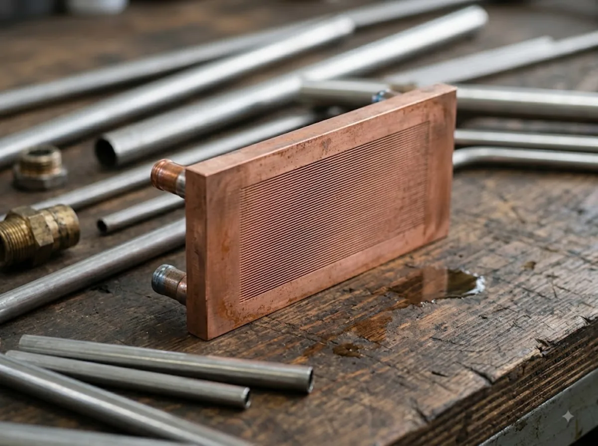
The coolant in an SFN is typically treated water or a water–propylene glycol mix. The loop is closed, runs warm, and feeds cold plates whose channels are a fraction of a millimeter wide. Three things follow from that.
Corrosion products have nowhere to go. In an open system, particles flush out. In a closed loop they circulate until they lodge somewhere — and the narrowest passage in the loop is inside a cold plate on top of a processor. A carbon steel or iron valve body sheds oxide into exactly the loop that can least tolerate it, which is why wetted-material guidance in the OCP water-quality documents leans on stainless steel and copper alloys and away from bare iron and mixed metals.
Mixed metals make their own battery. Aluminum cold plates, copper tubing, brass fittings and steel pumps in one loop create galvanic pairs the inhibitor package then has to fight. Every additional metal complicates the chemistry. Type 316 stainless — CF8M in its cast form — is broadly compatible with the coolant packages in common use and does not add a reactive metal to the mix.
Chlorides are the quiet risk. Make-up water and some cleaning agents bring chlorides into the loop, and chloride pitting is the failure mode that separates 316 from 304: the molybdenum in 316 resists it, 304 to a lesser degree. For a loop that is supposed to run for years without opening, the alloy step is small money.
Water, glycol and inhibitors
What actually circulates in the secondary loop is a chemistry decision, not an afterthought. Straight treated water carries the most heat per litre and is the default where the loop never sees freezing temperatures in transport or standby. Where it might, the industry blends in propylene glycol — preferred over ethylene glycol in and around occupied spaces for its lower toxicity — and accepts the penalty in heat capacity and viscosity that comes with it. Either way the fluid ships with an inhibitor package: chemicals chosen to passivate the specific metals the loop contains.
That last clause is why the wetted-materials list and the coolant specification are one decision wearing two hats. An inhibitor package is formulated against a known set of metals; every surprise alloy a component sneaks into the loop is a metal the chemistry was not designed to protect. A stainless valve body is the boring choice here in the best sense — it asks nothing extra of the inhibitors and contributes no ions of its own. The coolant supplier's compatibility sheet, not the valve catalogue, has the final word; the valve's job is to have nothing on that sheet to argue about.
Temperature, for once, is the easy part. Secondary loops run warm by design — supply setpoints in modern deployments sit in the range the ASHRAE datacom guidance describes for warm-water cooling, and even the hottest return leg is far below what a PTFE-seated stainless valve is rated for.
Pump head is a budget: valves and pressure drop
Short answer: every component in the secondary loop spends some of the pump's available head, valves included, and the loop designer's job is to spend it where it buys something. A valve's contribution is expressed as a flow coefficient, Cv — the flow in gallons per minute that produces a one-psi pressure drop across the valve. Higher Cv, lower loss. A full port ball valve in the open position has a bore equal to the pipe's inside diameter, so its Cv is high enough that the valve is nearly invisible to the pump; a reduced-port valve necks the flow down and back up, and pays for its smaller body with permanent head loss.
One reduced-port valve is harmless. A row of racks is another matter: an in-row loop can pass through a CDU connection, a header, a rack takeoff and a branch valve before it ever reaches a cold plate, and pressure drops add in series. Losses that were individually negligible stack into a number that decides whether the pumps hold their margin when the row is upgraded to hotter, thirstier silicon. The arithmetic is unforgiving in one direction only — nobody has ever regretted specifying the larger bore.
Two practical notes follow. First, pressure testing at commissioning briefly takes the loop above its operating pressure; components rated far above the working figure — the 1000 WOG class of a stainless process ball valve against a loop running well below 100 psi — turn that test into a non-event. Second, flow coefficients only mean anything with the valve fully open. Ball valves in an SFN should be specified and operated as on-off components; throttling a ball valve parks the seat edge in the flow and wears it. If a branch genuinely needs balancing, that is a job for a balancing valve, not a half-open ball.
Specifying the isolation valve
The workhorse of the list above is the full port ball valve. Here is what actually matters when you put one on a CDU drawing, in the order it tends to bite.
Full port, not reduced. Pump head in an SFN is a budget, and every reduced-port valve spends some of it. A full port bore matches the pipe inside diameter, so the valve adds almost nothing to loop resistance — the difference is invisible on a spec sheet and very visible on the pump curve.
Fewer joints, fewer leak paths. A liquid loop above live electronics is unforgiving of weeping joints. A two-piece body that is seal-welded rather than bolted removes the body joint as a leak path entirely — there is no gasketed flange between body halves to age, relax and seep.
Pressure margin costs nothing. Secondary loops operate at modest pressures, well below 100 psi in typical designs. A valve rated 1000 WOG is not overkill; it is a component that will never be the weakest point in the loop, including during pressure testing at commissioning.
Threads the loop can actually use. Small-bore SFN plumbing in North American builds runs NPT. Stock availability in NPT matters more than catalogs admit — a CDU production line does not wait six weeks for a valve.
Match the connection standard to the build, not the habit. North American CDU lines plumb small-bore connections in NPT; equipment built around Asian supply chains often arrives in PT (BSPT) taper thread instead, and the two look similar enough to cross-thread. A program that sources globally should write the thread standard on the drawing and hold every supplier to it. For hard-plumbed runs where no joint should ever weep, weld-end valves take the thread question off the table entirely — at the cost of committing the valve to the pipe, which is exactly why the serviceable three-piece and extended-weld constructions exist.
This is, transparently, the specification of our own V-2B two-piece ball valve: cast CF8M (316) body, seal-welded two-piece construction, full port, PTFE seats, 1000 WOG, −20°C to 180°C, eleven sizes from 1/4″ to 4″ with 316 + NPT ex stock. We did not design it for liquid cooling — it predates the AI boom by two decades — but the requirements list a CDU builder writes today maps almost line for line onto what a heavier-wall stainless process valve already is.
Check valves, strainers and drains: the unglamorous three
The isolation valve gets the attention, but three supporting players decide how the loop behaves on its worst day.
The check valve earns its keep at pump changeover. Redundant pumps are standard in CDUs, and a swing check on each discharge is what stops the running pump from short-circuiting flow backwards through its idle partner. A swing check closes by gravity and reverse flow alone — no springs to tire, no power, no signal. The one specification detail that matters is orientation: a swing check is built for a mounting position, and a horizontal-pattern valve belongs in horizontal pipe with the hinge up. Put it vertical and the disc may hang open; the datasheet position is part of the specification, not a suggestion.
The strainer is commissioning insurance first, running insurance second. A new loop carries the debris of its own construction — weld spatter, pipe dope, gasket fragments, the odd washer — and the first weeks of operation sweep all of it toward the narrowest passages. A Y strainer ahead of each pump catches that first harvest before it reaches seals and cold plates. The maintenance habit that makes it work: open the blowdown after the first days of operation, again at the first scheduled service, and then on whatever interval inspection justifies. A strainer nobody ever cleans is just a pressure drop with a screen in it.
Drains and vents are the difference between an hour and a weekend. Coolant loops get filled, flushed, sampled and partially drained over their lives. A drain ball valve at each low point gives that work a controlled path with a hose thread on the end; a vent at each high point lets air out so the fill actually fills. The alternative — cracking compression fittings and catching coolant in trays above live racks — is how loops end up on incident reports. Small full-port drain valves cost least at build time, which is exactly when nobody thinks they are needed.
What we make, and what we do not
Honesty section. SZ Valves is a stainless valve manufacturer with its own foundry in Taichung, Taiwan — we pour CF8 and CF8M castings and machine them in-house, and how that works is covered in our guide to evaluating a valve casting manufacturer.
We make the ball valves, check valves and strainers in the table above. We do not make CDUs, rack manifolds, quick disconnects, hoses or cold plates — those come from your own line or from specialists. Where we fit is as the valve supplier behind a CDU or manifold production run: repeat batches, consistent castings, material certificates with every shipment, and OEM terms including private labeling and customer part numbers marked on the body.
Qualifying a valve supplier for a CDU program
A CDU or manifold production line buys valves differently from a plant maintenance office. A plant buys ten; a program buys the same valve every month for years, and the risks that matter change accordingly. Five questions do most of the sorting.
Who pours the castings? A supplier with its own foundry controls alloy chemistry and traceability at the source; a trading company controls a purchase order. Both can deliver good product, but when a heat of castings is questioned, the distance between you and the furnace is measured in weeks. Our guide to evaluating a valve casting manufacturer covers what to ask.
Is the material certified per shipment? Wetted-material discipline in an SFN only works if every batch is what the drawing says. Mill certificates tied to each delivery — not a generic certificate on file — are the paper trail that makes an audit boring.
Is the specification stable across batches? Seat compound, stem seal, handle, marking: small substitutions that are invisible in a catalogue photograph surface as assembly-line stoppages. Repeat-batch consistency is a manufacturing habit, and it is worth asking a prospective supplier how they control it.
Can the valve carry your identity? OEM programs usually want the customer part number, logo or both on the body — laser marking at minimum, private label packaging where the valve ships in the end product's box. This is standard work for a manufacturer set up for OEM and an afterthought for one that is not.
What is actually on the shelf? Production lines schedule in weeks, not quarters. Knowing which sizes, materials and thread standards the supplier holds in stock — and which are made to order — belongs in the qualification conversation, not the first purchase order crisis.
Mistakes that show up after commissioning
No isolation at the manifold takeoffs. The loop works fine — until one branch needs service and the whole row has to come down with it. Branch valves are cheap at build time and miserable to retrofit.
Mixed metals nobody decided on. A brass valve here, a plated-steel fitting there, each individually harmless. The loop chemistry sees all of them at once. Decide the wetted-materials list once, then hold suppliers to it.
Spending pump head on cheap valves. Reduced-port valves at every takeoff quietly stack pressure drop until the pump runs out of margin at exactly the moment a rack is upgraded to hotter silicon.
No drain and vent points. Filling a loop through a cracked fitting and venting through a loosened plug works once, badly. Proper drain valves at low points and vents at high points turn a weekend job into an hour.
Skipping the commissioning flush. The strainer can only catch what the flow brings to it. A loop that goes straight from pressure test to production carries its construction debris into the cold plates on day one. Flush, clean the strainer screens, then hand over.
Throttling with ball valves. A half-open ball valve looks like flow balancing and acts like seat erosion. If branches need balancing, specify balancing hardware; keep the ball valves for what they are good at — being fully open for years and then sealing drop-tight when someone finally needs them to.
FAQ
What is a coolant distribution unit?
A coolant distribution unit (CDU) is a pumping and heat-exchange station that separates a facility's chilled water system from the closed coolant loop serving liquid-cooled IT equipment. It transfers heat between the two loops through a heat exchanger while keeping the fluids apart, and it controls flow, temperature and pressure on the IT side so cold plates receive clean, conditioned coolant rather than raw facility water.
What is the secondary fluid network?
The secondary fluid network (SFN) is the closed coolant loop on the IT side of the CDU. It runs from the CDU's supply connection through rack manifolds and branch lines to the cold plates on each server, then back through the return path. Because it is closed, fluid quality and wetted-material choices matter more than in open systems — anything corrosion releases into the loop stays in the loop.
What valves does a CDU need?
A typical layout uses full port ball valves at the CDU supply and return for isolation, small-bore ball valves at each rack manifold takeoff, swing check valves on pump discharges to stop reverse flow through an idle pump, drain valves at loop low points, and a Y strainer upstream of pumps. The common thread is serviceability: each valve exists so one component can be worked on without draining or stopping the rest of the loop.
Why is 316 stainless steel used in liquid cooling loops?
Three reasons. Closed loops trap corrosion products, and the narrow channels in cold plates are where circulating particles end up — stainless bodies shed essentially none. Mixed metals in one loop create galvanic corrosion pairs, and 316 avoids adding a reactive metal. And chlorides from make-up water or cleaning agents cause pitting that 316's molybdenum resists better than 304. The cast equivalent of 316 is CF8M, which is what a cast stainless valve body should specify.
Can you supply valves to CDU and manifold manufacturers?
Yes — that is the customer this article is written for. We supply stainless ball valves, check valves and Y strainers in repeat production batches, cast in our own foundry and machined in-house, with material certificates on every shipment. OEM terms include private labeling and your part number marked on the body. Send a drawing or a specification and we will quote against it. The steps from drawing to sample to production are on our custom valve manufacturing page.
Summary
A CDU and its secondary fluid network are a closed plumbing system with unusually low tolerance for leaks, particles and pressure loss. Valves decide whether that system can be serviced piece by piece or only all at once. Specify full port bores to protect pump head, seal-welded stainless bodies to remove leak paths and corrosion sources, check valves on paired pumps, and drain points you will be glad of a year later. None of it is exotic — it is process-piping discipline applied to a loop that happens to sit above expensive silicon.
If you are building CDUs, manifolds or complete cooling loops and need a stainless valve line behind them, we are a foundry-backed manufacturer set up for exactly that kind of repeat work.